Installation and electrical connection KNX presence detector mini with temperature measurement (and humidity measurement) and KNX brightness controller mini
The KNX presence detector mini with temperature measurement, the KNX presence detector mini with temperature and humidity measurement and the KNX brightness controller are designed for ceiling installation. The mounting in DIN 49073 flush-mounted housings or with a surface-mounted housing is possible. Note the operating instructions for this for KNX presence detector mini temperature measurement reference number 33700 1S .., KNX presence detector mini with temperature and humidity measurement reference number 33900 1S .. and KNX brightness controller mini reference number: 2092 LUX.
- Ensure that the mounting location is free of vibration.
- For optimum range, choose an interference-free installation location (you can find a detailed description in the operating instructions for KNX presence detector mini temperature measurement reference number 33700 1S .., KNX presence detector mini with temperature and humidity measurement reference number 33900 1S .. and KNX brightness controller mini reference number 2092 LUX).
- Mounting in the vicinity of electrical loads, radiators, cooling systems or external walls can negatively influence the temperature measurement of the presence detector.
KNX presence detector mini with temperature measurement and KNX presence detector mini with temperature and humidity measurement
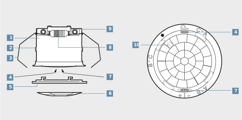
(1) Presence detector |
(2) Guide for clamping springs |
(3) Spring clip |
(4) Programming button, red |
(5) Design ring |
(6) Push-on cover |
(7) Humidity sensor opening, universal version |
(8) Bus connection |
(9) Wire fixing |
(10) Position of brightness sensor |
Instructions for Secure operation
- Activate secure commissioning in the ETS.
- Scan the device certificate or add it to the ETS project. It is recommended to use a high-resolution camera for scanning the QR code.
- Document all passwords and store them securely.
Mount and connect presence detector in false ceiling
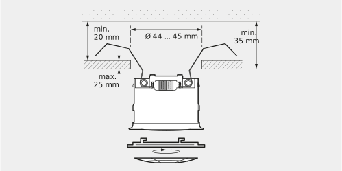
The following requirements must be fulfilled before mounting:
- The surroundings in the false ceiling must be dry.
- The max. thickness of the false ceiling is approx. 25 mm. The mounting depth must be at least 35 mm. The space between the concrete ceiling and the false ceiling must be at least 20 mm. The ceiling cutout is 44…45 mm.
Proceed as follows to mount and connect the presence detector in the false ceiling:
- Connect the bus line.
- Clamp the bus line with the wire fixing.
- Bend the spring clip back and push the presence detector into the false ceiling.
- Put the design ring on and rotate clockwise.
- Cut out the push-on cover if required and clip it into the design ring.
Install clamping springs for box mounting
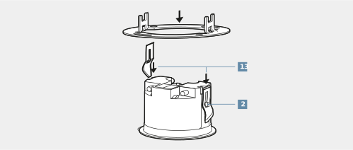
Proceed as follows to install the clamping springs for box mounting in a flush-mounted box or in a surface-mounted housing:
- Remove the spring clips (3).
- Push the clamping springs (13) from behind into the guides (2) until they click in.
Mounting and connecting presence detector in flush-mounted box
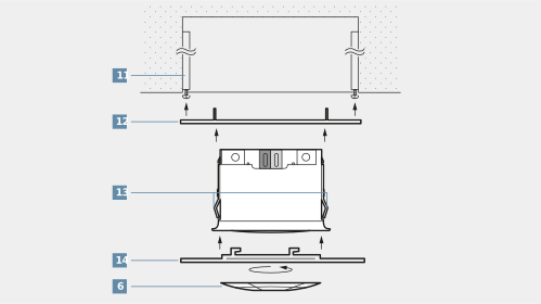
The following requirements must be fulfilled before mounting:
- The flush-mounted box (11) is mounted at the chosen installation location on the room ceiling.
- The spring clips (3) are removed and the clamping springs (13) are mounted.
Proceed as follows to mount and connect the presence detector in the flush-mounted box:
- Mount the supporting frame (12) on the flush-mounted box.
- Connect the bus line with the connection terminal.
- Click the presence detector into the supporting frame (12).
- Position the large design ring (14) and rotate clockwise.
- Cut out the push-on cover (6) if required and clip it into the design ring (14).
Mount and connect presence detector in a surface-mounted housing
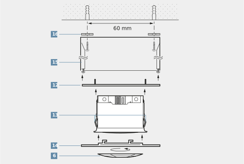
The following requirements must be fulfilled before mounting:
- The surface-mounted housing (15) is used.
- The supplied sealing gaskets (16) are applied to the screw holes on the surface-mounted housing if it is being installed in damp surroundings and it is an IP44 installation.
- The cable inlet has been sealed with the supplied rubber grommet. To this end, the rubber grommet must be cut out appropriately for the bus line and then the bus line is fed into the surface-mounted housing.
Proceed as follows to mount and connect the presence detector in a surface-mounted housing:
- Mount the surface-mounted housing (15) at the chosen installation location on the room ceiling. Note that the hole spacing must be 60 mm.
- Mount the supporting frame (12) on the surface-mounted housing (15).
- Connect the bus line with the connection terminal.
- Click the presence detector into the supporting frame (12).
- Position the large design ring (14) and rotate clockwise.
- Cut out the push-on cover (6) if required and clip it into the design ring (14).
KNX brightness controller mini
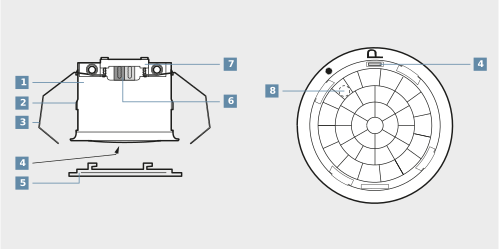
(1) Brightness controller |
(2) Guide for clamping springs |
(3) Spring clip |
(4) Programming button, red |
(5) Design ring |
(6) Bus connection |
(7) Wire fixing |
(8) Brightness sensor |
- The surroundings in the false ceiling must be dry.
Max. thickness of the false ceiling is approx. 25 mm, mounting depth at least 35 mm.
The space between the concrete ceiling and the false ceiling at least 20 mm. The ceiling cutout 44…45 mm. - Connect the bus line and clamp the bus line securely with the wire fixing (9) or (7).
- Bend the spring clip (3) back and push the device (1) into the false ceiling.
- Put the design ring (5) on and rotate clockwise.
The device is programmed with KNX-certified software.
- Connect the device.
- Ensure that the device is ready for use.
If the device is mounted, remove the design ring. - Switch on the bus voltage.
- Press the red programming button (4). The LED in the sensor window lights.
- Allocate the physical address. The LED goes out.
- Label the device on the side with the physical address.
- Load the application software into the device.
- Activate secure commissioning in the ETS with Secure operation.
Scan the device certificate or add it to the ETS project. It is recommended to use a high-resolution camera to scan the QR code. Document all passwords and store them securely - Check the detection ranges of each KNX device connected in parallel using the software.
You can find more detailed information in the operating instructions for KNX presence detector mini with temperature measurement reference number 33700 1S .., KNX presence detector mini with temperature and humidity measurement reference number 33900 1S .. and KNX brightness controller mini reference number 2092 LUX.