Installation and electrical connection of presence detector
- Ensure that the mounting location is free of vibration.
- For optimum range, ensure that the mounting location is free of interference (you can find a detailed description of the range in the operating instructions presence detector DWPM 17360 .. and DWPM K 360 ..).

(1) Terminal box |
(2) Sensor cover |
(3) Brightness sensor |
(4) Sensor window with red and blue indication LED |
(5) Decor ring |
(6) Push-on cover |
- Connect the flush-mounted insert correctly. This is not required for the DWPM K 360 .. because it has an integrated performance unit and is surface-mounted.
- You can reduce the detection range using a push-on cover. Using satellite units you can increase the detection range (see operating instructions presence detector DWPM 17360 .. and DWPM K 360 ..).
- Set the presence detector individually. You can find exact procedures in the respective operating instructions DWPM 17360 .. and DWPMK 360 .. .
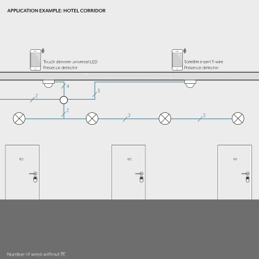
- Ensure that the mounting location is free of vibration.
- Avoid sources of interference, such as heating, ventilation or air conditioning systems in the detection range. Interference sources and cooling lamps can lead to unwanted detection.
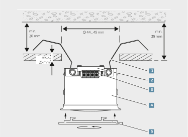
(1) Spring clip (2) Wire fixing (3) Terminal | (4) Motion detector (5) Design ring |
Usable conductor cross section | |
| 1 x 0.14 …0.5 mm² |
| 1 x 0.20 …0.5 mm² |
| 1 x 0.25 …0.5 mm² |


- Create a 44...45 mm diameter cutout in the ceiling.
Note that the surroundings in the false ceiling must be dry. The false ceiling thickness must be no more than 25 mm. The mounting depth of the motion detector must be a minimum of 35 mm. The distance between concrete ceiling and false ceiling must be a minimum of 20 mm. - As the power supply, use the unchoked output of a KNX power supply or the mains adapter with safety extra-low voltage.
- Connect the connection cable to the terminal.
- Secure the connection cable using the supplied wire fixing.
- Bend the spring clip back and push the motion detector into the false ceiling.
- Put the design ring on and rotate the ring clockwise.
Connection of motion detector mini basic and compatible devices
Connection to multi station 2570 M1SR or 2590 M1SR
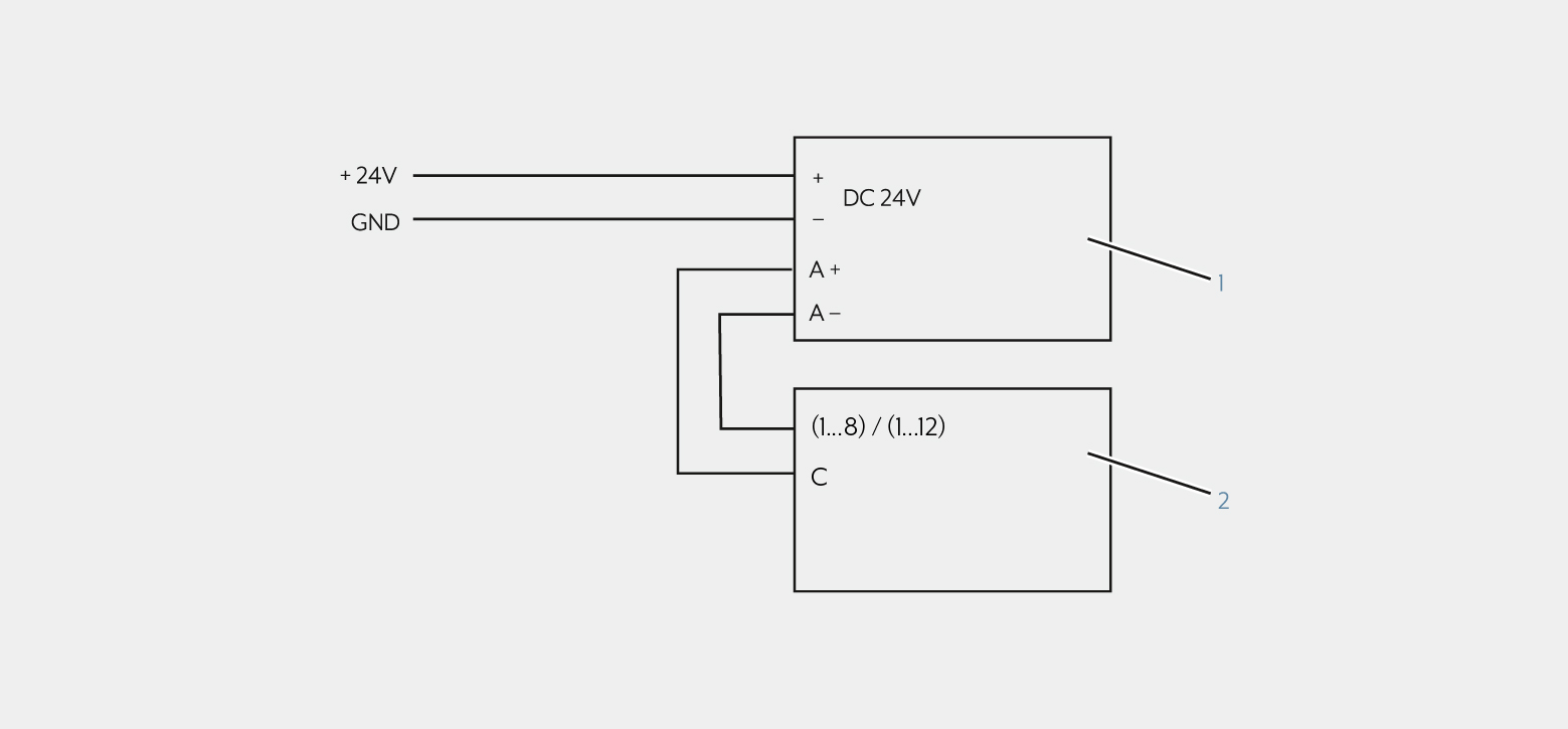
Item | Device | See also |
|---|---|---|
(1) | Motion detector Mini Basic | |
(2) | Multistation | https://www.jung-group.com/en-DE/p/KNX-multi-station... https://www.jung-group.com/en-DE/p/KNX-multi-station-universal... |
Connection to 6-gang binary input
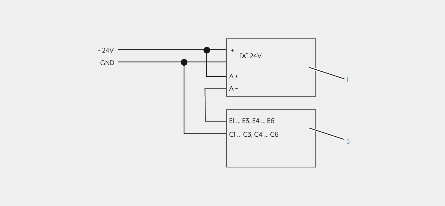
Item | Device | See also |
|---|---|---|
(1) | Motion detector Mini Basic | |
(3) | Binary input 6-gang |
Connection to push-button interface 2-gang, Secure or push-button interface 4-gang, Secure
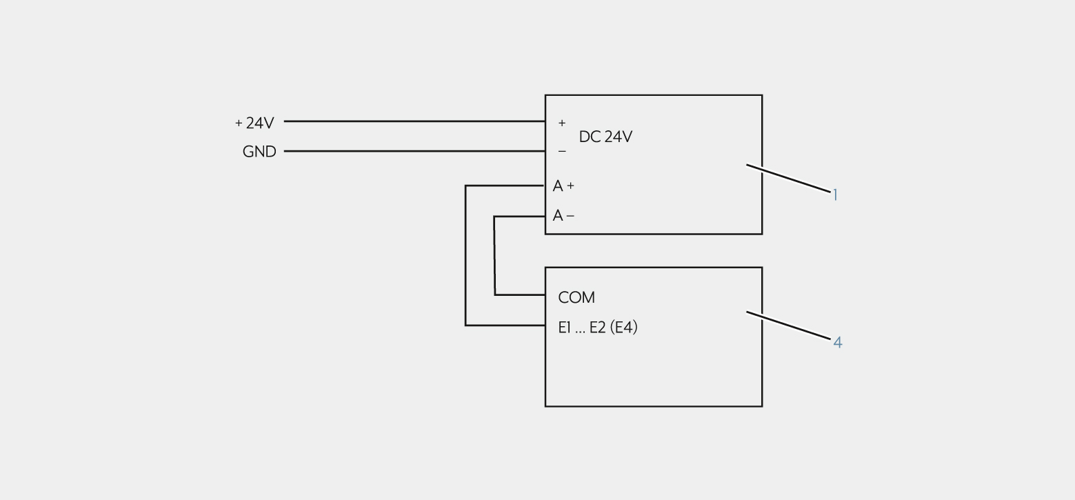
Item | Device | See also |
|---|---|---|
(1) | Motion detector Mini Basic | |
(4) | Push-button interface 2-gang, Secure/ |
Connection to switch actuator 2-gang, Secure
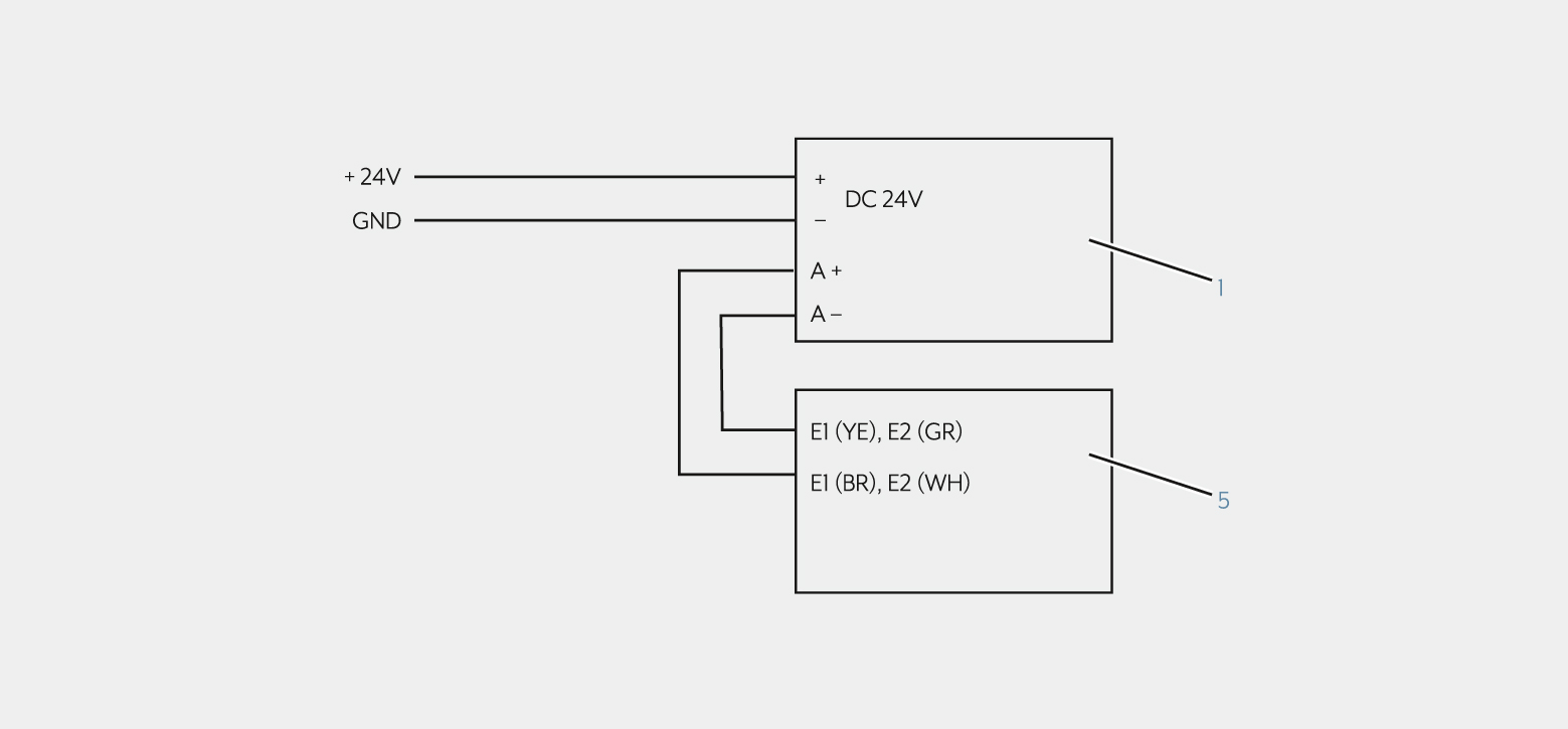
Item | Device | See also |
|---|---|---|
(1) | Motion detector Mini Basic | |
(5) | Switch actuator 2-gang, Secure |
Connection to 8-gang binary input
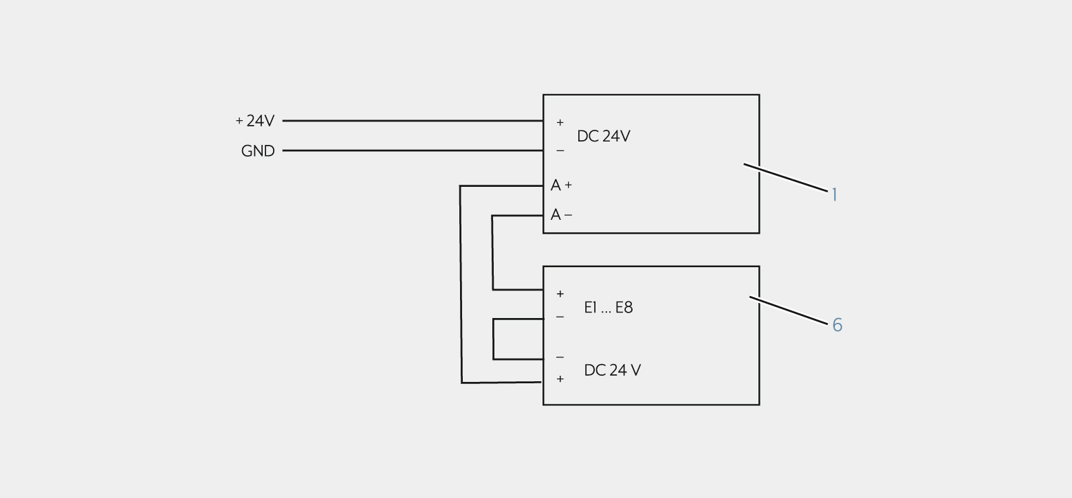
Item | Device | See also |
|---|---|---|
(1) | Motion detector Mini Basic | |
(6) | Binary input 8-gang |
Connection to KNX blinds actuator flush-mounted 1-gang, Secure with satellite unit actuator
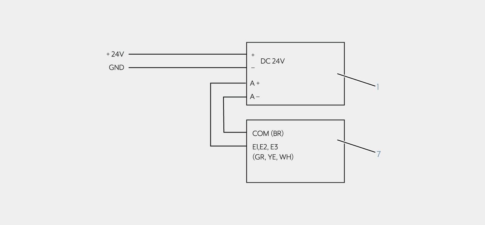
Item | Device | See also |
|---|---|---|
(1) | Motion detector Mini Basic | |
(7) | KNX flush-mounted blinds actuator, 1-gang, Secure with satellite input |