Installation and electrical connection
Satellite unit 1720 NE
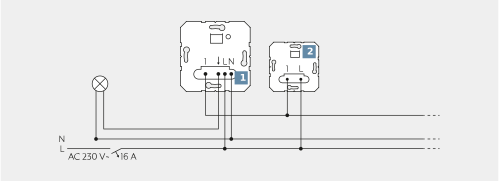
(1) a main unit |
(2) 2-wire satellite unit |
Any number of 2-wire satellite units can be connected to a main unit. |
Satellite unit 1723 NE
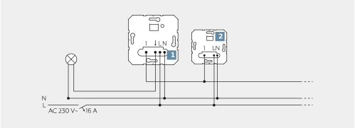
(1) a main unit |
(2) 3-wire satellite unit |
Any number of 3-wire satellite units can be connected to a main unit. |
Satellite unit 1723 NE
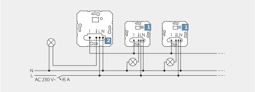
(1) multiple main units |
(2) 2-wire satellite unit |
Up to five same or different main units together with a 3-wire satellite unit can be controlled. |
Clampable conductor cross sections | |
|---|---|
| 1 x 0.5 ... 4 mm² |
2 x 0.5 ... 2.5 mm² | |
| 1 x 0.5 ... 4 mm² |
2 x 0.5 ... 2.5 mm² | |
| 1 x 0.5 ... 4 mm² |
2 x 0.5 ... 1.5 mm² | |


The function of the satellite unit is dependent on the insert and the cover of the main unit.
- Connect the satellite unit according to the connection diagram. Note the usable conductor cross sections.
- Mount the insert in the wall box. Ensure that the connection terminals are positioned at the bottom.
- Do not attach or replace the cover under voltage, otherwise this might cause malfunctions.
- Attach the frame to the cover.
- Switch on the mains voltage.
Power DALI push-button controller TW 1713 DSTE
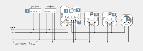
(1) DALI insert |
(2) Cover interface with LED |
(3) TEST button |
(4) DALI device |
(5) 3-wire satellite unit |
(6) 2-wire satellite unit |
(7) Push-button, normally open contact |
A 3-wire satellite unit can only control one DALI insert. Central control is not possible. |
Power DALI push-button controller TW 1713 DSTE
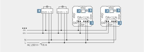
(1) DALI inserts |
(2) Cover interface with LED |
(3) TEST button |
(4) DALI device |
When switching multiple DALI inserts in parallel, ensure correct polarity. |
Clampable conductor cross sections | |
|---|---|
| 1 x 0.5 ... 4 mm² |
2 x 0.5 ... 2.5 mm² | |
| 1 x 0.5 ... 4 mm² |
2 x 0.5 ... 2.5 mm² | |
| 1 x 0.5 ... 4 mm² |
2 x 0.5 ... 1.5 mm² | |
- Connect the DALI insert (1) and DALI device (4) in accordance with the wiring diagram. Note the information from the manufacturer and the usable conductor cross section.
- If multiple circuit breakers supply dangerous voltages to a device or load, pair the circuit breakers or label them with a warning message such that disconnection from the mains is ensured.
- The connected DALI devices may be operated on different phases.
- Briefly operate the TEST button to switch the attached lighting even without a cover.
Depending on the cover, the DALI insert can switch lights, and set and save the brightness and colour temperature.
Power-DALI-2 174x DSTE
(1) DALI-2 insert |
(2) Cover interface with LED |
(3) TEST button |
(4) DALI-2 device |
(5) 3-wire satellite unit |
(6) 2-wire satellite unit |
(7) Push-button, normally open contact |
A 3-wire satellite unit can only control one DALI-2 insert. Central control is not possible. |
Clampable conductor cross sections | |
|---|---|
| 1 x 0.5 ... 4 mm² |
2 x 0.5 ... 2.5 mm² | |
| 1 x 0.5 ... 4 mm² |
2 x 0.5 ... 2.5 mm² | |
| 1 x 0.5 ... 4 mm² |
2 x 0.5 ... 1.5 mm² | |
- Connect the DALI-2 insert (1) and DALI-2 device (4) in accordance with the wiring diagram. Note the information from the manufacturer and the usable conductor cross section.
- If multiple circuit breakers supply dangerous voltages to a device or load, pair the circuit breakers or label them with a warning message such that disconnection from the mains is ensured.
- The connected DALI-2 devices may be operated on different phases.
- Briefly operate the TEST button to switch the attached lighting even without a cover.
Depending on the cover, the DALI-2 insert can switch lights, and set and save the brightness and colour temperature.
Pulse insert 1708 IE with staircase timer 1208 REG
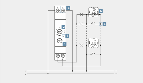
(1) Automatic switch for rail mounting |
(2) Adjuster, run-on time |
(3) LED |
(4) Adjuster, operating mode |
(5) Pulse insert with motion detector or Tastaufsatz |
(6) Push-button, normally open contact |
Pulse insert 1708 IE with staircase timer 1208 REG
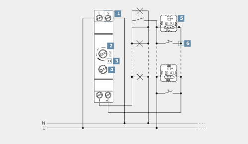
(1) Automatic switch for rail mounting |
(2) Adjuster, run-on time |
(3) LED |
(4) Adjuster, operating mode |
(5) Pulse insert with motion detector or Tastaufsatz |
(6) Push-button, normally open contact |
Clampable conductor cross sections | |||
|---|---|---|---|
Automatic switch for rail mounting | Pulse insert | ||
| 1 x 0.2 ... 4.0 mm² / 2 x 0.2 ... 4.0 mm² |
| 1 x 0.5 ... 4 mm² / 2 x 0.5 ... 2.5 mm² |
| 1 x 0.34 ... 4.0 mm² / 2 x 0.34 ... 4.0 mm² |
| 1 x 0.5 ... 4 mm² / 2 x 0.5 ... 2.5 mm² |
| 1 x 0.14 ... 2.5 mm² / 2 x 0.14 ... 2.5 mm² |
| 1 x 0.5 ... 4 mm² / 2 x 0.5 ...1.5 mm² |


Do not operate multiple automatic switch for rail mounting next to each other. Avoid nearby heat sources. Provide adequate heat removal.
- Note the usable conductor cross sections for automatic switch for rail mounting and pulse insert.
- Mount the automatic switch for rail mounting (1) on the DIN rail.
- Connect the automatic switch for rail mounting (1), pulse insert (5) and push-button (6) in accordance with the wiring diagram.
- Mount the pulse insert or push-button in the appliance box. Note that the connection terminals of the pulse insert must be positioned at the bottom.
- Mount frame and cover.
- If multiple circuit breakers supply dangerous voltages to a device or load, pair the circuit breakers or label them with a warning message such that disconnection from the mains is ensured.
- Set the run-on time and operating mode on the automatic switch for rail mounting:
CLOCK: automatic function without switch-off warning
CLOCK LIGHT: automatic function with switch-off warning
LIGHT BEAM: light is permanently on
LIGHT: light is permanently switched off. - For automatic function with switch-off warning, there can be a reduction in the lifetime of the relay contact when using fluorescent lamps or energy-saving lamps. The set run-on time extends by approx. 30 seconds.
- Set the brightness threshold and sensitivity on the movement detector cover. See instructions for the relevant cover.
In combination with a pulse insert, not all functions can be used on the motion detector.