Installation and electrical connection
Switch insert 1701 SE
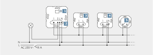
(1) TEST button |
(2) Switch insert |
(3) 2-wire satellite unit |
(4) 3-wire satellite unit |
(5) Push-button, normally open contact |
Switch insert 1702 SE
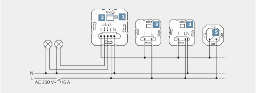
(1) TEST button |
(2) Display LED and connection socket for cover |
(3) 2-wire satellite unit |
(4) 3-wire satellite unit/rotary dimmer extension |
(5) Push-button, normally open contact |
Switch insert 1704 ESE
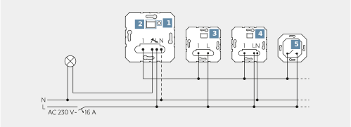
(1) TEST button |
(2) Display LED and connection socket for cover |
(3) 2-wire satellite unit |
(4) 3-wire satellite unit |
(5) Push-button, normally open contact |
Clampable conductor cross sections | LED signalling | ||
|---|---|---|---|
| 1 x 0.5 ... 4 mm² | LED colour | Specified run-on time |
2 x 0.5 ... 2.5 mm² | green | Switch without run-on time | |
| 1 x 0.5 ... 4 mm² | Ivory | Run-on time:: 1 minute |
2 x 0.5 ... 2.5 mm² | Blue | Run-on time:: 5 minutes | |
| 1 x 0.5 ... 4 mm² | Yellow | Run-on time:: 30 minutes |
2 x 0.5 ... 1.5 mm² | red | Run-on time:: 60 minutes | |


- Connect the switch insert according to the connection diagram. Note the usable conductor cross section.
- Optionally connect the 2-wire satellite unit (3), 3-wire satellite unit (4) and push-button, normally open contact (5).
- Mount the switch insert in the appliance box. Ensure that the connection terminals are positioned at the bottom.
- Do not attach or replace the cover under voltage, otherwise this might cause malfunctions.
- Attach the frame and cover.
- Switch on the mains voltage.
- The load can be switched by briefly pressing the TEST button (1).
- Set the run-on time.
- Press the TEST button (1) for longer than 4 seconds.
- Release the TEST button (1) briefly and then press the TEST button (1) so often until the LED lights in the colour of the desired run-on time (see table). This is automatically saved after 30 seconds or after pressing the TEST button (1) for approx. 4 seconds. The save process was successful if the LED extinguishes.