Mounting and electrical connection of the LB Management motion detectors standard 1.1 m and 2.2 m
- Ensure that the mounting location is free of vibration.
- For an optimum range, select the installation location such that it is tangential to the direction of movement (you can find a detailed description of the range in the LB Management operating instructions for motion detectors standard reference number .. 17180 .. and .. 17280 ..).
- Avoid sources of interference in the detection range.
- Connect the flush-mounted insert correctly.
- To ensure a degree of protection of IP 44, additional mounting steps are necessary (see sealing kit instructions).
- Attach the cover with frame to the flush-mounted insert.
- You can reduce the detection range using a push-on cover. Using satellite units you can increase the detection range (see LB Management operating instructions for motion detectors reference number .. 17180 .. and .. 17280 ..).
- Set the brightness threshold and the sensitivity.
- With the motion detector cover 1.10 m, the adjuster is behind the cover.
- With the motion detector cover 2.20 m, the adjuster is on the reverse of the device. The run-on time cannot be changed.
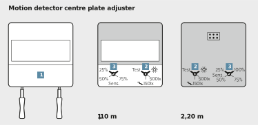
- Remove the centre plate (1) carefully with a screwdriver.
- Set the brightness threshold on the covers of the main unit and on all satellite units.
- Turn adjuster (2) to one of the four defined values:
TEST | Testing the detection range |
|---|---|
| Daytime operation: the motion detector operates brightness-independent. |
500lx | individual setting |
| Setting for stairways according to DIN EN12464-1. |


- Set the desired sensitivity at the adjuster (3).
- Test the detection range by rotating the adjuster (2) to TEST.