Installation and settings
Connecting and fitting the system insert
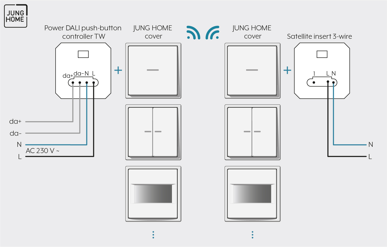
Note the following for the installation:
- Ensure that the control cable with regards type, cross-section and routing complies with the VDE specifications for 250 V cables, control voltage has basic insulation.
- The control cable and load cable can be run in a shared cable, e.g. NYM J 5×1.5.
- The connected DALI devices may be operated on different phases.
Proceed as follows for mounting:
- Connect the system insert according to the connection diagram. In the process, observe the clampable cable cross-sections and the instructions of the electronic ballast manufacturer.
- Pair the circuit breakers or label them with a warning message such that disconnection is ensured when multiple circuit breakers supply dangerous voltages to a device or load.
Clampable conductor cross-sections | |
|---|---|
| 1 x 0.5 ... 4 mm² 2 x 0.5 ... 2.5 mm² |
| 1 x 0.5 ... 4 mm² 2 x 0.5 ... 2.5 mm² |
| 1 x 0.5 ... 4 mm² 2 x 0.5 ... 1.5 mm² |


