Installation and settings
The room thermostat insert has six terminals N, L, heating (output), C (cooling input), 2x external temperature sensor connection for external temperature measurement.
The line conductor is connected to L and the neutral conductor to N. The connection for cooling is made on C and for heating on heating. The external temperature sensor for external temperature measurement is connected to the two external temperature sensor connections.
Connecting and fitting the system insert
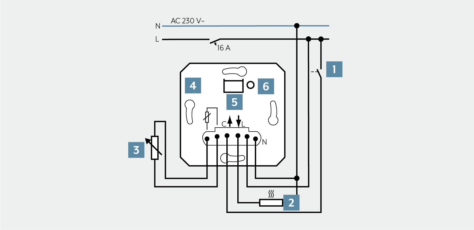
1 | Switching contact for switching to cooling |
2 | Electric underfloor heating system or electrothermal valve drive |
3 | External temperature sensor for external temperature measurement (variable resistance) |
4 | Room thermostat insert |
5 | Cover interface with LED |
6 | TEST button |
Note the following for the installation:
Proceed as follows for mounting:
- Connect the room thermostat insert according to the wiring diagram.
- Mount the room thermostat insert in a wall box. In doing so, the connection terminals must be facing down. Sufficient connection space remains thanks to its installation depth of only 24 mm.
- Attach the frame and cover to the room thermostat insert.
- Switch on the mains voltage.
- With the TEST button, you can switch the load.
- The LED for the cover is illuminated when the load is switched on.
- If there is 230 V at input C, cooling is active.
Note
The room thermostat insert only functions with room thermostat covers. All other attachments have no function.
Clampable conductor cross-sections | |
|---|---|
| 1 x 0.5 ... 4 mm² 2 x 0.5 ... 2.5 mm² |
| 1 x 0.5 ... 4 mm² 2 x 0.5 ... 2.5 mm² |
| 1 x 0.5 ... 4 mm² 2 x 0.5 ... 1.5 mm² |


