Installation and settings
Connecting and mounting JUNG HOME Puck dimmer 1-gang with 2 binary inputs
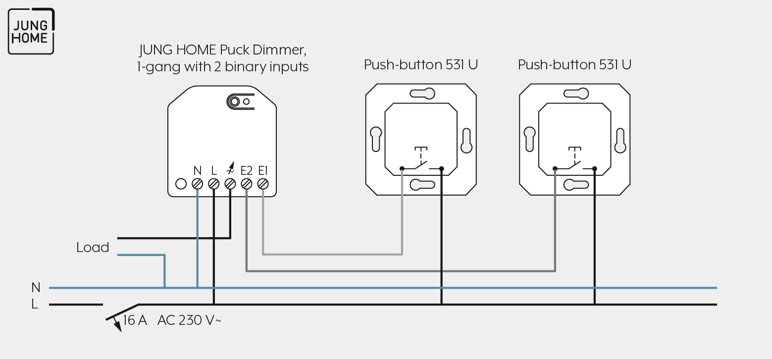
Below you can see an example for connecting the devices. Further examples for other connection possibilities can be found in the operating instructions for the JUNG HOME Puck dimmer 1-gang with 2 binary inputs.
Note the following for the mounting:
Proceed as follows for mounting:
- Connect the dimming actuator, push-button and the load in accordance with the connection example.
Observe the clampable conductor cross sections.
Illuminated push-buttons must have a separate terminal for N conductor.
Connect a maximum of 600 W of LED lamps per 16 A circuit breaker. In addition, observe the information of the transformer manufacturer for the connection of electrical transformers. - Position the JUNG HOME dimming actuator in the wall box such that the Prog button and the status LED are visible.
- Switch on the mains voltage.
The load at both outputs can be partially switched by briefly pressing the Prog button. - Mount the appropriate cover.
CLAMPABLE CONDUCTOR CROSS SECTION | |
|---|---|
| 1 x 0.5 … 4 mm² |
| 1 x 0.5 … 4 mm² |
| 1 x 0.5 … 2.5 mm² |


Commissioning
For how to commission the JUNG HOME Puck dimmer 1-gang with 2 binary inputs using the JUNG HOME app, see Chapter "Pair device".