Installation and settings
The blind inserts have four terminals L, N, Up and Down for the control of a motor for the shading system.
The line conductor is connected to L and the neutral conductor to N. The two terminals Up and Down are available for the connection of an on-site motor of the shading system.
Connecting and fitting the system insert
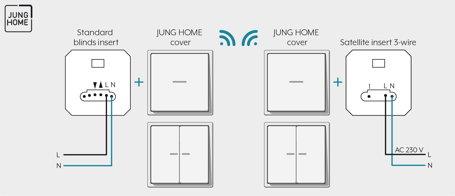
Note the following for the installation:
Proceed as follows for mounting:
- Connect the blind insert according to the connection plan.
- Mount the blind insert in a device socket. In doing so, the connection terminals must be facing down. Sufficient connection space remains thanks to its installation depth of only 24 mm.
- Switch on the mains power.
- With the TEST button, you can also control the attached motor without a cover to test the wiring and to configure the end position of the motor.
- If you press TEST for less than a second, blinds, shutters or awnings move towards the lower end position.
- If you press TEST for longer than one second, blinds, shutters or awnings move in the direction of the upper end position.
- If you press TEST longer than four seconds, the motor stops.
- If the motor moves in the incorrect direction, operate the TEST button for more than ten seconds. This reverses the polarity of the motor outputs (Up/Down) and removal of the inserts again is not necessary. - Set the top and bottom positions depending on the blind type. Details for this can be found in the operating manuals of the motors. Set the desired limit position for the motor.
- Then attach the frame and attachment in the de-energised state.
Clampable conductor cross-sections | |
|---|---|
| 1 x 0.5 ... 4 mm² 2 x 0.5 ... 2.5 mm² |
| 1 x 0.5 ... 4 mm² 2 x 0.5 ... 2.5 mm² |
| 1 x 0.5 ... 4 mm² 2 x 0.5 ... 1.5 mm² |


